<assembly.referencesurface />
assembly.referencesurface defines a named mounting frame as a direct child of
assembly.part or
assembly.printedpart. It adds no solid geometry.
A reference surface can anchor other parts even when its owner has no CAD model.
Mount a printed lampshade on a stem
The base's stem surface is 12 mm above its origin. The hollow printed stem mates
its downward-facing base surface to it, then supplies a shade surface 80 mm
above its own origin. The shade's mounting collar sits at local Z = 0; its
stem surface faces down toward the lamp.
This example lifts the shade 60 mm for assembly. Set its mountGap to zero to
seat the collar on the stem at world Z = 92 mm. The shade is a hollow tapered
shell with three spokes connecting its wall to the collar, and the stem has a
channel for wiring.
import { assembly, jscad } from "tscircuit"
import type { JscadOperation } from "jscad-planner"

export default function Lamp() {
return (
  <assembly.device name="LAMP">
    <assembly.part name="BASE" cadModel={{ jscad: lampBase }}>
      <assembly.referencesurface
        name="stem"
        width="28mm"
        height="28mm"
        centerZOffset="12mm"
      />
    </assembly.part>
    <assembly.printedpart
      name="STEM"
      material="petg"
      color="#436f8b"
      jscad={<LampStem />}
      mountedTo="BASE.stem"
      mountFace="base"
    >
      <assembly.referencesurface
        name="base"
        width="28mm"
        height="28mm"
        normalDirection="z-"
      />
      <assembly.referencesurface
        name="shade"
        width="28mm"
        height="28mm"
        centerZOffset="80mm"
      />
      <assembly.part
        name="BULB"
        cadModel={{
          jscad: {
            type: "colorize",
            color: [1, 0.9, 0.65],
            shape: {
              type: "union",
              shapes: [
                {
                  type: "cylinder",
                  radius: 2,
                  height: 8,
                  center: [0, 0, 84],
                },
                { type: "sphere", radius: 7, center: [0, 0, 88] },
              ],
            },
          },
        }}
      />
    </assembly.printedpart>
    <assembly.printedpart
      name="SHADE"
      material="pla"
      color="#d9a15f"
      jscad={<LampShade />}
      mountedTo="STEM.shade"
      mountFace="stem"
      mountGap="60mm"
    >
      <assembly.referencesurface
        name="stem"
        width="28mm"
        height="28mm"
        normalDirection="z-"
      />
    </assembly.printedpart>
  </assembly.device>
)
}

/** Part-local, right-handed XYZ in mm, +Z up. The base's top is Z=12;
* the stem is 80 mm tall. The shade's mounting collar starts at its local Z=0,
* with an open tapered shell spanning Z=-24..20. Reference frames add no mesh.
*/
const lampBase: JscadOperation = {
type: "colorize",
color: [0.08, 0.12, 0.16],
shape: {
  type: "subtract",
  shapes: [
    {
      type: "union",
      shapes: [
        { type: "cylinder", radius: 34, height: 8, center: [0, 0, 4] },
        { type: "cylinder", radius: 24, height: 4, center: [0, 0, 10] },
      ],
    },
    { type: "cylinder", radius: 2, height: 14, center: [0, 0, 6] },
    {
      type: "translate",
      vector: [17, 0, 1],
      shape: { type: "cuboid", size: [34, 4, 3] },
    },
  ],
},
}

function LampStem() {
return (
  <jscad.colorize color="#436f8b">
    <jscad.subtract>
      <jscad.cylinder radius={4} height={80} center={[0, 0, 40]} />
      <jscad.cylinder radius={2} height={82} center={[0, 0, 40]} />
    </jscad.subtract>
  </jscad.colorize>
)
}

function LampShade() {
return (
  <jscad.colorize color="#d9a15f">
    <jscad.union>
      <jscad.subtract>
        <jscad.hull>
          <jscad.cylinder radius={36} height={0.2} center={[0, 0, -23.9]} />
          <jscad.cylinder radius={20} height={0.2} center={[0, 0, 19.9]} />
        </jscad.hull>
        <jscad.hull>
          <jscad.cylinder radius={34.4} height={0.2} center={[0, 0, -25]} />
          <jscad.cylinder radius={17.6} height={0.2} center={[0, 0, 21]} />
        </jscad.hull>
      </jscad.subtract>
      <jscad.subtract>
        <jscad.cylinder radius={7} height={4} center={[0, 0, 2]} />
        <jscad.cylinder radius={2.2} height={6} center={[0, 0, 2]} />
      </jscad.subtract>
      {[0, 120, 240].map((angle) => (
        <jscad.rotate key={angle} angles={[0, 0, (angle * Math.PI) / 180]}>
          <jscad.cuboid size={[20, 2, 2]} center={[16, 0, 2]} />
        </jscad.rotate>
      ))}
    </jscad.union>
  </jscad.colorize>
)
}
Surface properties
| Property | Default | Description |
|---|---|---|
name | "anchor" | Name unique within the owning part, including named JSCAD references. Mount to it with PART.name. |
shape | "rect" | Rectangular reference frame; the only supported shape. |
plane | "xy" | Local "xy", "xz", or "yz" plane. |
normalDirection | Depends on plane | Outward direction: "x+", "x-", "y+", "y-", "z+", or "z-". Must be perpendicular to the plane. |
centerXOffset | 0 | Surface center's X offset from the part origin. |
centerYOffset | 0 | Surface center's Y offset from the part origin. |
centerZOffset | 0 | Surface center's Z offset from the part origin. |
width, height | Omitted | Optional positive rectangular extents. Supply both together. Mounting uses the center, not the edges. |
Offsets and extents accept millimetres as numbers or unit strings such as "1mm".
They use the part's local, right-handed XYZ frame: +X right, +Y top, and +Z above.
CAD model position and rotation offsets affect the model, not these mounting frames.
| Plane | Allowed normals | Default normal | In-plane X direction |
|---|---|---|---|
xy | z+, z- | z+ | x+ |
xz | y+, y- | y+ | x+ |
yz | x+, x- | x+ | y+ |
Reversing the normal keeps the in-plane X direction. The second tangent follows
the right-handed frame; for example, XZ with y+ has its second tangent along −Z.
Attach to a named surface
On a printed part or motor, supply mountedTo="PART.surface" and mountFace
together. The target and mating faces meet with opposing outward normals and
aligned in-plane X directions. mountGap defaults to zero; a positive value
separates the faces along the target's outward normal.
A board needs only mountedTo="PART.surface". Its target must be parallel to XY.
The board keeps its PCB world placement, and the attached parts move to meet it.
One board can anchor each connected assembly. Targets resolve within the same
assembly.device, including parts declared later. Missing surfaces, duplicate
names, and attachment cycles are errors.
Child surfaces work with imported CAD models as well as JSCAD geometry. Existing
named <jscad.rectangle reference /> faces remain supported on printed parts;
use distinct names when combining the two forms.
Inspect reference surfaces in a 3D export
Enable showReferenceSurfaces when converting Circuit JSON to GLTF or GLB:
import { convertCircuitJsonToGltf } from "circuit-json-to-gltf"

const glb = await convertCircuitJsonToGltf(circuit.getCircuitJson(), {
  format: "glb",
  showReferenceSurfaces: true,
})
This option defaults to false. Cyan rectangles and PART.surface labels identify
the frames; orange arrows show their outward normals. Explicit width and
height set the rectangle size. Frames without extents use a 10 mm diagnostic
rectangle.
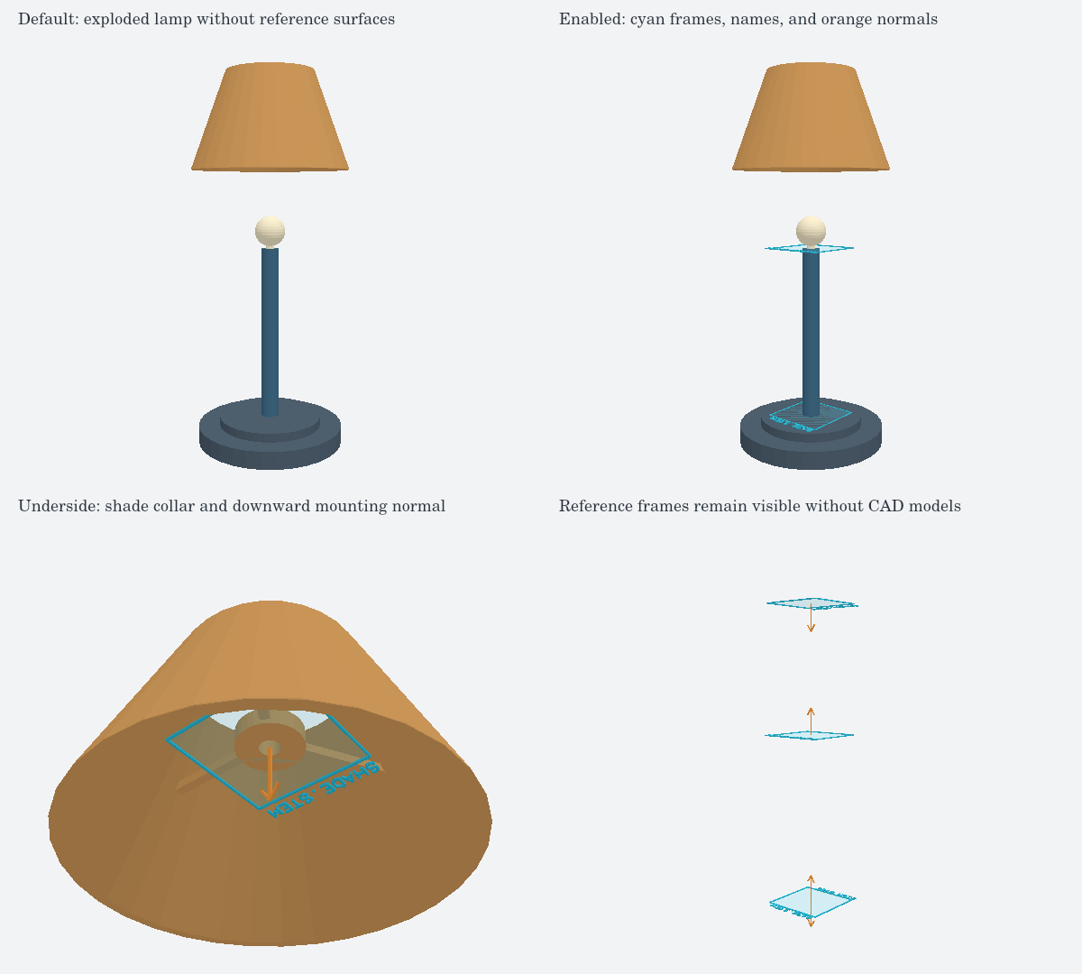
Core emits the resolved frames as cad_reference_surface records in Circuit
JSON, including frames on parts without geometry. Each record belongs to its
owning source component and contains the world-space center, normal, and X
tangent. pcbDisabled suppresses these CAD records.